3D model description
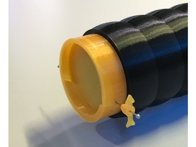
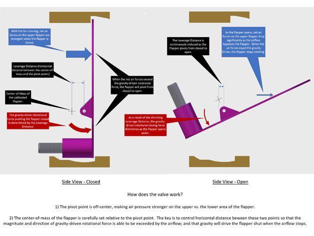
I designed this to prevent damp external air from back-flowing into my printer enclosure when my exhaust fan is idle. The valve opens automatically when the fan starts, and the valve closes when the fan stops. The valve is very sensitive: it opens wide with my fan set to it's slowest speed; when the airflow stops the valve closes fully against the edge stops.
I integrated this valve into my HEPA Air Filter Scrubber Tower https://cults3d.com/en/3d-model/tool/hepa-air-filter-scrubber-tower, and this valve is backward compatible (as an add on) with the Air Filter design from https://www.thingiverse.com/thing:2394452
The design primarily consists of a Collar, and a Flapper. The outer diameter of the 42mm Collar mates with the interior of the Grommet provided at https://www.thingiverse.com/thing:2394452
3D printing settings
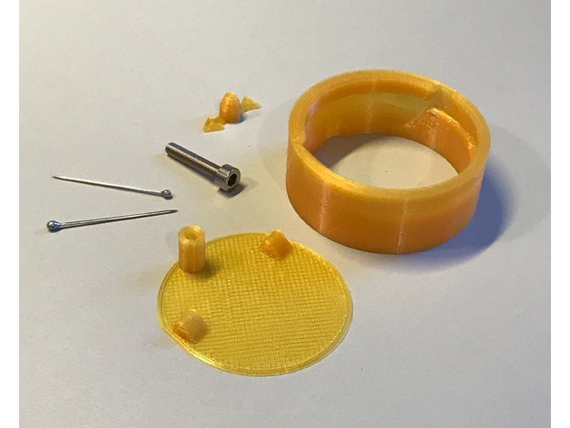
Bill of Materials
Print with PLA at 0.2mm layers:
Collar (supports)
Flapper (no supports) - Wait for the part to completely cool before lifting it off of the build plate. While still warm, the Flapper is prone to being bent. It is only two layers thick.
Rotation Indicator (no supports)
Other Items
2 straight pins (e.g. for sewing; these will be about 0.65mm diameter and 20mm long).
1 M3 screw at least 10 mm long
Superglue
Assembly
The goal is to calibrate the Flapper to be at rest in a near-LEVEL position. The top and bottom of the Flapper should be at the same height as the sides when the Flapper is suspended from it's hinge points.
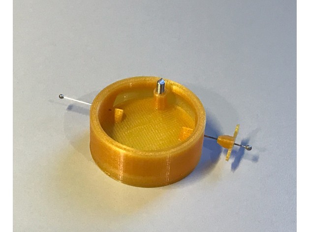
Insert a straight pin into each axle hole on the Flapper hinge. Do not force the pins through the holes. The holes are intended to hold the sharp tips of the pins snugly.
Make a counter-weight by cutting the head off of the M3 screw so that you have a section of threaded rod that is about 8mm long.
Twist the counter-weight (one or two turns, max) into the hole on the Flapper. The counter-weight should be on the same side of the Flapper as the pins.
Balance the straight pins across the opening of a small drinking glass, with the Flapper suspended in the middle of the glass opening. The Flapper should rotate without obstructions.
Allow the flapper to come to rest. If the flapper does not lay flat (parallel with the rim of the glass, with the counter-weight vertical and facing down); then remove some material from the counter weight, or cut a new longer piece of threaded rod. I used heavy-duty pliers to cut the M3 screw. Try to get the balanced Flapper to be less than 10 degrees off of horizontal. It is better to have a slightly too-heavy counter-weight, vs. slightly too-light.
After balancing the Flapper, super-glue the counter-weight to the Flapper.
Remove the pins from the Flapper.
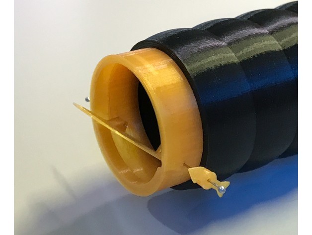
Insert the Flapper into the Collar, and rotate the Flapper so that it's oriented parallel to the Collar. The hinges on the Flapper should line up with holes on either side of the Collar.
Slide the Rotation Indicator onto one of the pins.
Insert the pins through the holes on either side of the Collar, with the tips of the pins reaching into the Flapper hinges. The pins must spin freely within these collar holes. Work the pins back-and-forth within the holes to push aside material that might be squeezing on the sides of the pins. With a pin resting horizontally in either hole, the pin should slide out as soon as you start rotating the the hole toward vertical. If the holes are too small for your pins, try printing the alternate collar with the larger pin holes.
Test the Valve: Hold the Collar vertical, with counter-weight at the bottom. The Flapper should self-close in a vertical position, and it should rotate without obstructions 67 degrees to an open position. A slight puff of air on the counter-weight side of the Flapper should be enough to open the Valve. The valve should completely self-close when the air stops moving.
Super-glue the tips of the pins to the Flapper.
Super-glue the Rotation Indicator to the shaft of one of the pins.
The final installation of the Valve must be oriented with the pin axles horizontal, and the closed flapper vertical.
https://vimeo.com/252888749
:format(webp)/https://fbi.cults3d.com/uploaders/13539655/illustration-file/1d201363-fad8-4937-bdbd-08c9162c4848/9f9aec65677f2a2fd962a7446016bb2f_preview_featured.jpg)


:format(webp)/https://fbi.cults3d.com/uploaders/13539655/illustration-file/5fa64a1a-df71-42bb-a1a6-e1667c7b64f6/6caa24a976900d28b86efbe3ee14265f_display_large.jpg)
:format(webp)/https://fbi.cults3d.com/uploaders/13539655/illustration-file/f3b65ac7-7a64-4d1d-b4c7-29ea4604d5f3/74aacdbee228949b0fad315f7f600438_display_large.jpg)
:format(webp)/https://fbi.cults3d.com/uploaders/13539655/illustration-file/cfa6e957-f626-46a0-8393-487d36cc6dce/3f82a77882196183a0b77badbe7801b5_preview_featured.jpg)
:format(webp)/https://fbi.cults3d.com/uploaders/13539655/illustration-file/38ce4224-99f0-41eb-b667-a48098601f4a/APC_0066.jpg)